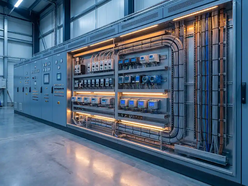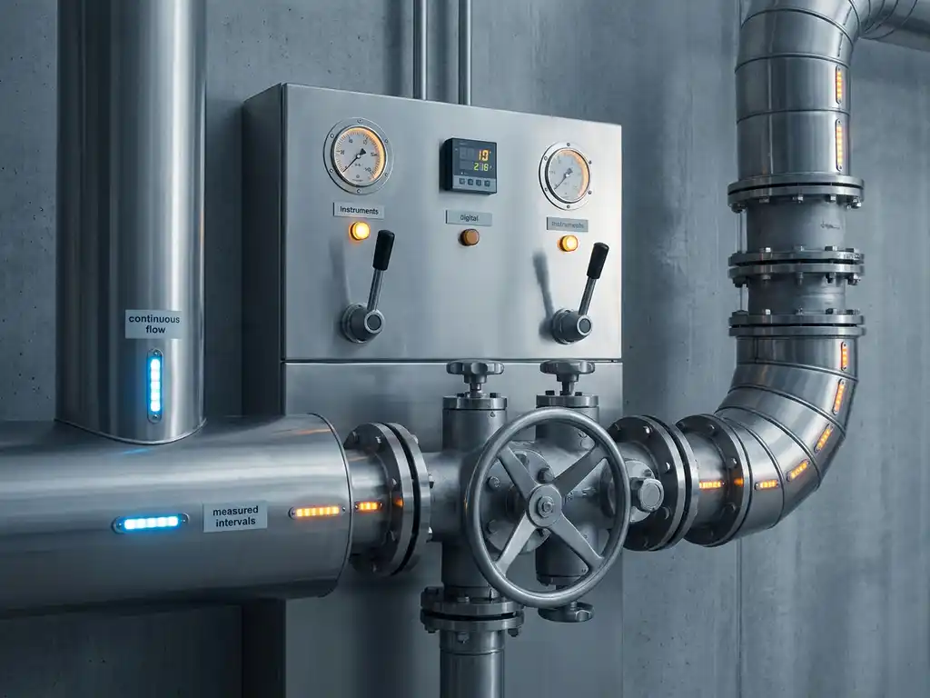

Analog inputs in a PLC system are the channels that receive continuously variable electrical signals from sensors and field devices, converting real-world physical measurements like temperature, pressure, and flow into numerical values the controller can process. Without analog inputs, a PLC could only detect whether something is on or off, making it impossible to monitor or control processes that require precise measurement. The sections below answer the most common questions about how analog inputs work, how to configure them, and when to use them.
How do analog inputs actually work inside a PLC?
A PLC analog input works by receiving a continuous electrical signal from a field device, typically a 4-20 mA current loop or a 0-10 V voltage signal, and passing it through an analog-to-digital converter (ADC). The ADC samples the signal at regular intervals and converts it into a digital integer value that the PLC’s CPU can read, store, and act upon in its control logic.
The resolution of the ADC determines how finely the input can distinguish between signal levels. A 12-bit ADC, for example, divides the full signal range into 4,096 discrete steps. A 16-bit ADC offers 65,536 steps, giving far greater measurement precision for applications where small changes in a process variable matter. The higher the resolution, the more faithfully the digital value reflects the actual physical measurement.
Each analog input module on a Siemens PLC, for instance, contains dedicated circuitry for signal conditioning, filtering, and conversion. The module isolates the incoming signal, removes high-frequency noise, and delivers a clean digital value to the process image of the CPU, where it becomes available to the control program on every scan cycle.
What types of sensors connect to analog inputs in a PLC?
The most common sensors that connect to PLC analog inputs are temperature sensors, pressure transmitters, flow meters, level sensors, and position transducers. These devices all produce a continuously variable output signal proportional to the physical quantity they measure, making them natural candidates for analog input channels rather than digital ones.
Current loop transmitters operating at 4-20 mA are the dominant standard in industrial environments because the current signal is largely immune to voltage drops caused by cable resistance. The 4 mA live zero also makes it easy to detect a broken wire, since a true zero reading is distinguishable from a failed circuit. Voltage-output sensors, typically 0-10 V or 0-5 V, are common in shorter cable runs where signal integrity is easier to maintain.
Thermocouples and resistance temperature detectors (RTDs) are a special case. They produce very low-level signals that require dedicated input modules with built-in compensation and amplification. Most modern PLC platforms, including Siemens SIMATIC hardware, offer specific thermocouple and RTD input modules that handle this signal conditioning automatically, so the engineering team does not need to design external conditioning circuits.
What is the difference between analog and digital inputs in a PLC?
The key difference between analog and digital inputs in a PLC is that digital inputs represent only two states, on or off, while analog inputs represent a continuous range of values. A digital input tells the PLC whether a switch is open or closed. An analog input tells the PLC exactly how much pressure, temperature, or flow is present at any given moment.
Digital inputs are simpler, faster, and less expensive to implement. They are ideal for detecting events such as a motor reaching its end position, a valve fully opening, or a level switch triggering an alarm. The signal is either a logic 1 or a logic 0, and there is no scaling or conversion required beyond reading the binary state.
Analog inputs require more engineering effort. The raw digital value from the ADC must be scaled to engineering units, noise filtering must be considered, and wiring practices matter significantly. However, the information they provide is far richer. A pressure transmitter connected to an analog input can tell the system whether pressure is rising slowly, holding steady, or spiking dangerously, giving the control program the data it needs to respond proportionally rather than just reactively.
Why do analog input signals lose accuracy in industrial environments?
Analog input signals lose accuracy in industrial environments primarily because of electromagnetic interference, ground loops, temperature drift, and poor wiring practices. These factors introduce noise or offset into the electrical signal before it even reaches the PLC module, causing the measured value to deviate from the true process variable.
Electromagnetic interference is generated by variable frequency drives, large motors, contactors, and power cables running parallel to signal wiring. This interference induces small voltages or currents into the analog signal cable, which the ADC then converts into erroneous readings. Shielded twisted-pair cable, with the shield grounded at one end only, is the standard countermeasure.
Ground loops occur when two pieces of equipment connected by a signal cable have different ground potentials. The resulting current flows through the signal circuit and adds an offset to the measured value. Galvanic isolation in the input module breaks this loop and restores measurement accuracy. Most quality analog input modules include isolation as a standard feature.
Temperature drift affects both the sensor itself and the input module electronics. Components change their electrical characteristics as temperature changes, introducing a slow offset that grows over time. Regular calibration of sensors and using modules rated for the ambient temperature range of the installation both help manage this effect.
How do you scale and configure analog inputs in a PLC program?
Scaling an analog input in a PLC program means converting the raw integer value from the ADC into a meaningful engineering unit such as degrees Celsius, bar, or liters per minute. This is done using a linear scaling function that maps the minimum and maximum raw counts to the minimum and maximum physical values of the sensor range.
In Siemens SIMATIC PCS 7 and TIA Portal environments, this scaling is typically handled by dedicated function blocks or normalization instructions. The engineer defines the low and high end of the sensor range in the hardware configuration, and the system either scales automatically or provides a normalized floating-point value that a simple multiplication and offset can convert to engineering units.
Configuration also involves setting the input type, current or voltage, the measurement range, the filter time constant, and the behavior on wire break. Getting these settings right in the hardware configuration is just as important as the software scaling. A misconfigured input type will produce readings that are numerically plausible but physically meaningless, which can be difficult to diagnose during commissioning.
For critical measurements, it is good practice to add limit checking in the control program. If the scaled value falls below the physical minimum or above the physical maximum of the sensor, the program should raise a diagnostic alarm rather than allowing an out-of-range value to propagate through the control logic.
When should you use analog inputs versus fieldbus communication?
You should use traditional analog inputs when you need simple, low-cost connections for individual sensors, when the installation environment does not support network infrastructure, or when the sensor does not have a digital communication interface. Fieldbus communication becomes the better choice when you need diagnostic data from smart instruments, when you are connecting many devices in a single cable run, or when configuration flexibility is a priority.
Analog inputs are well understood, easy to troubleshoot with a multimeter, and work reliably even in electrically noisy environments when wired correctly. For a single pressure transmitter feeding a control loop, a 4-20 mA connection to an analog input module is often the most straightforward and cost-effective solution.
Fieldbus protocols such as PROFIBUS PA, FOUNDATION Fieldbus, or HART give smart transmitters the ability to send not just the primary process variable but also secondary variables, device status, and calibration data over the same cable. This is particularly valuable in large installations where hundreds of instruments are connected, because the diagnostic information available over the fieldbus can dramatically reduce the time needed to identify and resolve measurement problems.
In practice, modern industrial facilities use both. Plant automation projects typically combine analog inputs for straightforward measurements with fieldbus connections for smart instruments where diagnostics and remote configuration justify the additional engineering investment. The decision comes down to the value of the diagnostic data, the complexity of the installation, and the capabilities of the instruments being used.
How CoNet helps with analog input configuration and PLC automation
Configuring analog inputs correctly, from hardware selection and wiring design through to scaling, filtering, and diagnostics in the control program, requires both broad knowledge of signal types and deep familiarity with the PLC platform in use. This is exactly where we add value for our clients.
As a Siemens specialist, we support the full lifecycle of analog input implementation across Siemens SIMATIC hardware and PCS 7 process automation systems. Here is what that looks like in practice:
- Hardware selection and module configuration: We advise on the right analog input modules for the signal types, resolution requirements, and environmental conditions of your installation.
- Wiring and earthing design: We apply proven practices to minimize interference and ground loops before they become measurement problems.
- Software scaling and diagnostics: We configure scaling, limit monitoring, and wire-break detection in the control program so your operators always have reliable process values.
- Fieldbus integration: Where smart instruments and PROFIBUS PA or HART communication are involved, we handle the integration alongside conventional analog inputs within the same system architecture.
- Troubleshooting and optimization: If existing analog measurements are unreliable or poorly scaled, we diagnose the root cause and implement a lasting solution.
Whether you are designing a new installation, expanding an existing plant, or dealing with persistent measurement issues, we are ready to help. Contact us to discuss your analog input challenges and find out how we can support your automation project.