A PLC system consists of four main components: hardware elements (CPU, power supply, I/O modules), programming software, communication interfaces, and memory units. These programmable logic controllers serve as the central brain of industrial automation, processing inputs from sensors and field devices to control outputs such as motors and valves. Each component works together to create reliable, flexible automation solutions that can be programmed and reconfigured for different manufacturing processes.
What exactly is a PLC system and why is it essential for industrial automation?
A PLC (Programmable Logic Controller) is a ruggedized digital computer designed specifically for controlling industrial machinery and processes in real time. Unlike standard computers, PLCs are built to withstand harsh industrial environments, including extreme temperatures, vibrations, electrical interference, and dust.
PLCs function as the central nervous system of automated manufacturing operations. They continuously monitor inputs from sensors, switches, and measuring devices, then execute programmed logic to control outputs such as motors, valves, lights, and alarms. This real-time processing capability allows for precise control of complex industrial processes.
The essential nature of PLCs in modern industry stems from their ability to replace traditional relay-based control systems. Whereas older systems required extensive hardwiring and physical modifications for changes, PLCs offer programmable flexibility. Manufacturers can modify control logic through software updates rather than rewiring entire control panels, significantly reducing downtime and maintenance costs.
PLCs have become indispensable because they provide reliable, repeatable control while offering the flexibility to adapt to changing production requirements. They integrate seamlessly with other industrial systems, enabling comprehensive process automation that improves efficiency, quality, and safety across manufacturing operations.
What are the core hardware components that make up every PLC system?
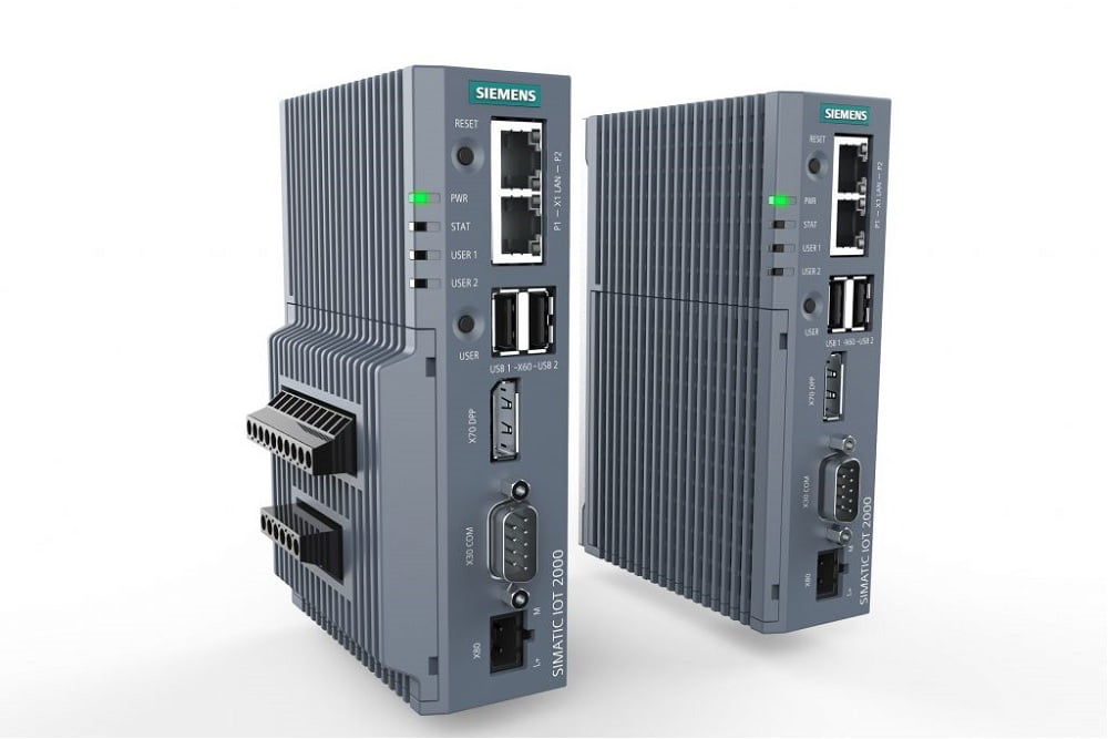
Every PLC system contains five essential hardware components: the CPU module, power supply unit, input/output modules, memory units, and communication interfaces. Each component plays a critical role in overall system functionality and reliability.
The CPU module serves as the brain of the PLC system. It executes the control program, processes input signals, and determines appropriate output responses. Modern CPU modules contain microprocessors capable of handling complex calculations, data manipulation, and communication tasks. The CPU also manages system diagnostics and error handling.
The power supply unit converts incoming AC voltage to the low-voltage DC power required by PLC components. Industrial power supplies are designed for reliability and often include backup capabilities to maintain operation during brief power interruptions. Proper power supply sizing ensures stable operation of all connected modules.
Memory units store the control program, configuration data, and operational values. PLCs typically use both volatile RAM for active program execution and non-volatile memory (EEPROM or flash) for permanent program storage. Memory capacity determines the complexity of programs the PLC can handle.
Communication interfaces enable PLCs to connect with other systems, including human-machine interfaces (HMIs), supervisory control systems, and other PLCs. These interfaces support various industrial communication protocols, allowing integration into broader automation networks.
How do input and output modules actually work in PLC systems?
Input and output (I/O) modules serve as the interface between the PLC’s digital processing unit and real-world devices. Input modules convert field signals into digital data the CPU can process, while output modules convert CPU decisions into signals that control field devices.
Digital input modules receive on/off signals from devices such as push buttons, limit switches, and proximity sensors. These modules convert various voltage levels (typically 24 V DC or 120/240 V AC) into logic signals the CPU recognizes. Each input is electrically isolated to prevent interference and protect the CPU from voltage spikes.
Analog input modules handle continuously variable signals from sensors measuring temperature, pressure, flow, or level. These modules contain analog-to-digital converters that translate sensor signals (such as 4–20 mA or 0–10 V) into numerical values the CPU can use for precise process control calculations.
Digital output modules control discrete devices such as motor starters, solenoid valves, and indicator lights. They provide switching capability to turn devices on or off based on CPU commands. Output modules include protective circuits and status indicators for troubleshooting.
Analog output modules generate variable control signals for devices such as variable frequency drives and control valves. These modules use digital-to-analog converters to produce precise output signals that enable smooth, proportional control of process variables.
Module selection depends on signal types, voltage levels, current requirements, and environmental conditions. Proper I/O configuration ensures reliable communication between the PLC and field devices while providing necessary isolation and protection.
What software components are required to program and operate PLC systems?
PLC software components include programming environments, runtime systems, human-machine interfaces, and communication protocols. These software elements work together to enable system configuration, program development, monitoring, and control functionality.
Programming software provides the development environment where engineers create, test, and download control programs to PLCs. Modern programming packages support multiple programming languages, including ladder logic, function block diagrams, and structured text. These tools include simulation capabilities, debugging features, and documentation functions.
The runtime system executes within the PLC CPU, managing program execution, I/O communication, and system diagnostics. This embedded software handles the continuous scan cycle that reads inputs, executes control logic, and updates outputs. Runtime systems also manage memory allocation and error handling.
Human-machine interfaces (HMIs) provide operator interaction capabilities through graphical displays, alarm management, and data logging functions. HMI software creates visual representations of processes, allowing operators to monitor system status and make necessary adjustments.
Communication protocols enable data exchange between PLCs and other systems. Industrial protocols such as Profibus, EtherNet/IP, and Modbus facilitate integration with enterprise systems, remote monitoring capabilities, and distributed control architectures.
Configuration software manages system setup, including I/O assignment, communication parameters, and security settings. This software ensures proper integration of all hardware and software components into a functioning automation system.
Understanding PLC components enables better decision-making when implementing process automation solutions. Whether upgrading existing systems or designing new installations, knowledge of these fundamental elements helps ensure reliable, efficient industrial automation that meets specific operational requirements.