
A PLC handles multiple simultaneous process inputs by reading all of them in a single, sequential scan cycle rather than processing each one the moment it changes. During each cycle, the controller reads the current state of every input, executes the control logic, and updates all outputs before starting the next cycle. The sections below unpack how that cycle works, what happens at the edges, and when the standard approach needs reinforcement.
How does a PLC scan cycle process inputs?
During a PLC scan cycle, the controller reads the state of every connected input in sequence, stores those values in an input image table in memory, runs the user program against that snapshot, and then writes the results to an output image table before updating the physical outputs. This entire process repeats continuously, typically hundreds of times per second.
The key concept here is the input image table. Rather than reading a live signal mid-execution, the PLC works from a frozen snapshot taken at the start of each scan. This means all logic within a single cycle operates on a consistent, coherent view of the process, regardless of how many inputs are connected. Whether the system has 10 digital inputs or 500, the scan cycle reads them all before a single line of logic runs.
This architecture is what makes PLC-based plant automation so reliable in industrial environments. The deterministic, repeatable nature of the scan cycle ensures that control logic always sees a stable input state, reducing the risk of erratic behavior caused by signal fluctuations mid-cycle.
What happens when two inputs change at exactly the same time?
When two inputs change simultaneously, a standard PLC treats them as equal because both new states are captured in the same input image scan. Neither input is prioritized over the other. The control logic processes both updated values together in that cycle, and the outputs respond accordingly.
In practice, “exactly simultaneous” is rare at the hardware level, but the effect is the same for any two changes that occur within the same scan window. Both are captured, and both are processed. This is one of the reasons the scan cycle model works well for most industrial control tasks: it naturally handles concurrent state changes without requiring complex arbitration logic.
The exception arises when two inputs change in rapid succession across a scan boundary. If input A changes just before the scan reads it and input B changes just after, input B will not be seen until the following cycle. For most process applications, this sub-millisecond delay is inconsequential. For high-speed or safety-critical applications, interrupt handling or hardware timestamping addresses this gap.
How fast does a PLC scan cycle run?
A typical PLC scan cycle runs between 1 and 50 milliseconds, depending on the processor speed, the size of the user program, and the number of I/O points. High-performance PLCs used in fast motion or safety applications can achieve cycle times below 1 millisecond, while larger distributed control systems may run longer cycles without any loss of process control quality.
Scan time is not fixed. It varies based on:
- The volume and complexity of the control logic being executed
- The number of physical I/O modules being scanned
- Communication overhead from networked I/O or HMI systems
- Any interrupt routines that temporarily suspend the main scan
For most process industries such as chemical production, food and beverage, or energy, a scan cycle in the 10 to 20 millisecond range is more than sufficient. The physical processes involved simply do not change faster than the controller can respond.
What’s the difference between interrupt-driven and cyclic PLC input handling?
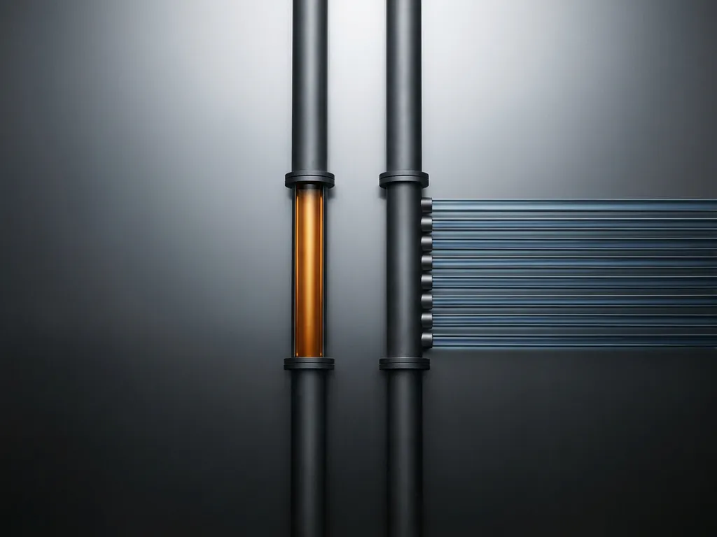
Cyclic input handling reads all inputs at the start of every scan, regardless of whether they have changed. Interrupt-driven handling triggers an immediate response the moment a specific input changes, suspending the normal scan cycle to execute a dedicated routine. Interrupt-driven handling is faster but more complex; cyclic handling is simpler, more predictable, and sufficient for the vast majority of industrial applications.
Cyclic handling
In cyclic mode, the PLC follows its fixed scan sequence every cycle. Every input is read, every output is updated, and the program runs in full. This predictability makes cyclic PLCs easy to program, debug, and validate. Process industries overwhelmingly rely on this model because their physical processes evolve over seconds or minutes, not microseconds.
Interrupt-driven handling
Interrupt routines are reserved for inputs that demand an immediate response faster than the scan cycle can deliver. A high-speed encoder pulse, an emergency stop signal, or a hardware fault detection event might all trigger an interrupt. The main program pauses, the interrupt service routine runs, and then normal scanning resumes. Overusing interrupts introduces complexity and can make system behavior harder to trace during troubleshooting.
How does a PLC handle analog inputs differently from digital inputs?
Digital inputs are binary: on or off. A PLC reads them as a single bit and stores the result instantly. Analog inputs carry a continuous signal, typically a current or voltage representing a measured value such as temperature, pressure, or flow. The PLC must convert this signal through an analog-to-digital converter (ADC) before it can be stored and processed, which adds a small conversion time and introduces the concept of signal resolution.
Analog input modules sample their channels at a defined rate, often independently of the main scan cycle. The converted value is placed in a memory register where the PLC logic can read it during the input image update. Because analog signals are continuous, the PLC logic works with the most recently converted value rather than a truly instantaneous reading.
This distinction matters in practice. A digital limit switch either trips or it does not. An analog pressure transmitter produces a value that drifts continuously, and the quality of that reading depends on the ADC resolution (typically 12 to 16 bits), the sample rate of the module, and any filtering applied to reduce electrical noise. Proper configuration of analog input modules is essential for accurate process measurement.
When does a PLC need additional hardware to manage high input volumes?
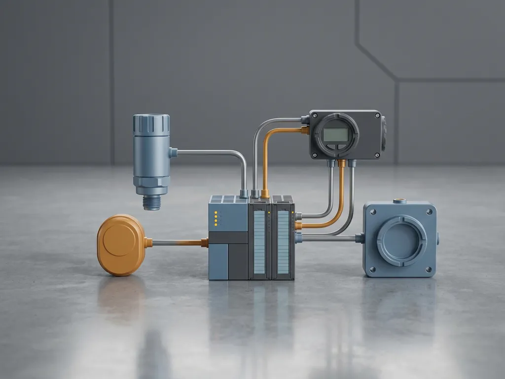
A PLC needs additional hardware when the number of I/O points exceeds the capacity of the base unit, when inputs are physically distributed across a large facility, or when scan time starts to degrade because the processor is reading too many modules in a single cycle. In these situations, distributed I/O systems, remote I/O racks, or dedicated co-processors are used to extend capacity without overloading the central controller.
Common scenarios that require expanded hardware include:
- Large production facilities where sensors are spread across multiple buildings or process units
- Systems with hundreds of analog inputs that each require individual ADC processing
- Safety-critical applications where inputs must be read by redundant processors simultaneously
- High-speed applications where a dedicated fast I/O module handles time-critical signals independently
Modern distributed control architectures, such as those built on Siemens SIMATIC PCS 7, address this by placing I/O processing closer to the field devices and communicating over industrial networks like PROFIBUS or PROFINET. This reduces the burden on the central processor and keeps scan times consistent even as the system scales.
How CoNet helps with PLC input handling and process automation
We at CoNet work with industrial automation systems every day, and PLC I/O architecture is at the core of what we design, configure, and optimize for our clients. Whether you are building a new system or troubleshooting an existing one, we bring the engineering depth to get it right. Here is what we offer:
- I/O architecture design: We assess your process requirements and design an input handling structure that matches your scan time needs, signal types, and volume of I/O points
- Distributed I/O planning: For large or geographically spread facilities, we design PROFIBUS and PROFINET-based distributed I/O systems that scale without compromising performance
- Analog input configuration: We configure ADC resolution, filtering, and sampling rates to ensure accurate, stable process measurements
- Interrupt and safety logic: For time-critical or safety-relevant inputs, we implement and validate interrupt routines and redundant input processing
- Siemens SIMATIC PCS 7 expertise: As the only PCS 7 Process Safety Specialist in the Netherlands, we bring certified knowledge to every project
If you want to discuss how your current PLC setup handles process inputs, or if you are planning a new automation project, get in touch with us and we will help you find the right solution.